Viruscraft: tangible interface electronics
Posted June 27, 2018 by Dave GriffithsWe needed to get a working prototype of our tangible interface running for the second Viruscraft workshop, so that we could have a complete system up and running from the custom hardware to the on-screen game world for people to test and give us feedback on how it worked.

You can read Amber's full report on this workshop here.
A recap on how this is supposed to work - we need to plug different types of ligand (protrusions on the outside of viruses that allow them to attach to cells in order to infect them) into a large wooden model virus capsid (the body of the virus) that we are building for use in exhibitions. The choices of shape you pick affects which host species your virus can infect on a simulation that is being run in real time. The best ligand shapes to use will change over time, as the hosts adapt to your mutations.

We decided to start by using a simple conductivity system to detect which ligand shape is plugged in, with three sets of three pairs of conductive pads on each triangle face of the capsid that can be connected (or not) with strips of copper on the bases of the ligands. This means we can detect between 7 different shapes in total. It's very cheap and simple, but a conductivity measurement like this will never be 100% accurate, which is why we are doing it in triplicate - the redundancy allows us some leeway if they are not plugged fully in, but this also results in a lot of connections we need test.

We started by using 6 digital inputs on a Raspberry Pi GPIO - just reading two sets of connectors on one triangle. Even with the triple redundancy, the connection across the pads is never going to be perfectly conductive, so in order to increase the sensitivity of the digital inputs (which need quite a bit of voltage to register as 'on' without extra circuitry) we added gigantic pull up resistors (22 Mohm). This means they default to on (+5V) but with very little current passing through - so a tiny amount of conductivity to ground will drop the voltage enough to register as 'off'. This means they are so sensitive that you can trigger a change just by bridging the gap on the pads with your fingers - this is exactly the same way that MakeyMakeys work.
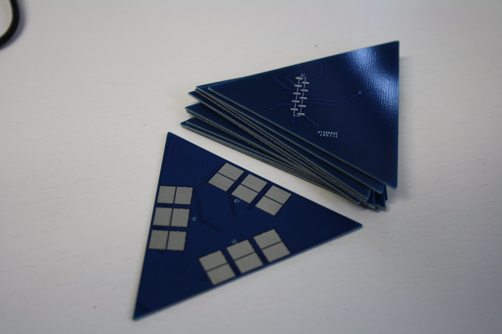
Based on our previous experiences with the self-etched PCBs we designed some neater ones that we could get manufactured so they would be consistent. In the meantime we have also recently got our hands on a CNC mill we can use for future PCB construction like this - but haven't quite had time to get it set up for production yet.
The next step was to come up with a more scalable way to read the signals, by moving everything onto a ATmega328 microcontroller - which is much cheaper than a Pi and suitable to embed in a custom circuit. The first plan was to keep it simple for the workshop and use 18 of its i/o pins to directly read just 2 triangles, so we could quickly get on with the job of connecting it to the game world. We didn't have time to get a PCB specifically designed for this, so I used strip board for rapid construction, just a few days before the workshop. To speed things up a bit I tried using KiCAD to help with the layout design.

Although KiCAD is not really designed for strip board it works quite well if you stick to a few rules. You set the grid to 2.54mm (1/10 inch) and use the lower copper side to represent the strips - drawing each one as you need them and leaving spaces to indicate where you need to cut the copper tracks. The top side copper layer is used to plan where the jumper wires will be placed to connect across the tracks where needed. The idea is to minimise these wires to make it simpler to build - and KiCAD is good for checking the circuit is correct for you as you organise everything. We then printed each side out on paper for reference, and glued the bottom side to the board to indicate where to cut the tracks.
One advantage of prototyping in strip board rather than making PCBs is that it's much easier to modify things in an adhoc manner. For example, halfway through building this we made the wooden parts of the capsid structure, and thought it would be a better demonstration to use 3 or more faces for the workshop if we could. At this point we could use a multiplexer chip to allow the microcontroller to select which triangle it is reading and share the 9 digital pins between all the triangles connected, in order to read each one in turn. This would mean we could use a single microcontroller to read 16 (or more) entire triangles (144 digital signals) rather than just 2 (18 signals) which is probably be enough in fact for the final design.


To do this we used a 74HC4067 multiplexer chip left over from the flotsam tangible programming project. These work like a general purpose digitally controlled switch, allowing you to connect a single pin to one of 16 connections and select them using 4 inputs as a binary address. We can now use this chip to select which face is connected to ground, meaning that the microcontroller would only be able to read the connections for that one face - even though they are all sharing the same microcontroller input pins.
This seemed to work well on the breadboard, but has a big problem that in the pre-workshop rush gave me a frustrating time to figure out precisely. When a selected face has a connection on the same position as another face which is currently unselected by the multiplexer, the ground connection loops back round the circuit to the unselected face too. If that unselected face also has a connection across the pads in a location that the selected face doesn't, then the microcontroller will mistakenly read that as a connection signal as well as it will be grounded and effectively read both of them at the same time.
The problem is that this only happens in particular arrangements of ligand codes, which means the interference doesn't always occur. In order to prevent this grounding problem where it 'leaks out' to the rest of the circuit the fix is to add diodes to each separate face connection, which only allow the current to move in one direction.
So this simple conductivity system turned out to not be quite so simple as hoped!

Emergency diodes...

Connecting this to the simulation, which is running in the browser (entering the world of the web) was actually much less of a problem than that of stray electrons. The microcontroller is connected to a Raspberry Pi via i2c serial for data - this setup is borrowed from the pattern matrix, which means the Raspberry Pi can read part the microcontroller's memory. A python script reads the state of the ligands over i2c and overwrites a text file each time a change is detected. This text file is accessible to a web server that is also hosting the game. The code running on the browser (in this case on the workshop participant's laptops, but eventually on an exhibition computer) reads this text file every second and updates the virus that is used for the simulation automatically when it is changed by a player.
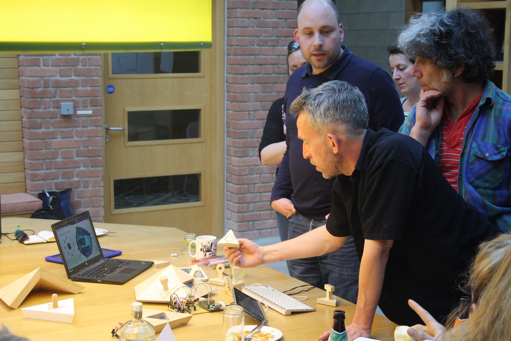
In the workshop we used the Raspberry Pi to serve the game over a wifi hotspot that people could connect their devices to, and we could get participants to test the tangible interface by adding/changing ligands. As they did this it would mutate the virus running in all their simulation worlds so they could see what was happening on the physical virus - and the hosts would get infected by the new virus on each player's world.
Created: 15 Jul 2021 / Updated: 15 Jul 2021
