Step by step: building tangible livecoded braid robots
Posted Sept. 11, 2020 by Dave GriffithsAfter successfully performing maypole dances and creating simple twists and weaves with hundreds of passers by at the Algomech festival in Sheffield, we noticed how much people like to interact with our woven robots - wanting to help or direct their actions by picking them up and trying to understand what they are doing.
As we are interested in tangible programming - where we move code from its conventional visual screen based domain into a touchable physical thinking form (inspired by our ancient weaver-coder ancestors), it was an important realisation that the robots themselves are in fact a potential tangible interface for thinking with.
Following this reasoning, is there some way we can embed code into their environment - if so, could this be a way to allow people to control them in their own space (rather than from say a separate, remote interface, as is more usual).
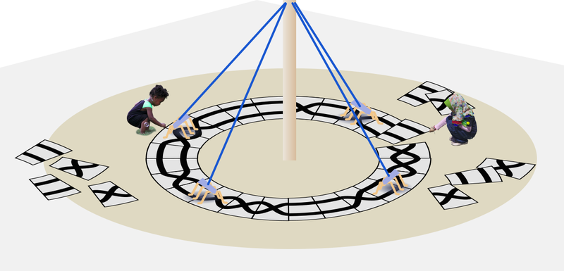
May pole dances are braids, complex mathematical structures which are created by multiple participants. If the robots can follow paths set by their programmers (perhaps by placing tiles as in the concept sketch above) - we might be able to use them to interactively explore the properties of woven braids. This idea might seem strange, but industrial robots for example in Amazon warehouses, use navigation lines and bar codes on the floor as environmental code to direct them to the right packages.
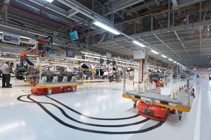
(An industrial style robot braid pattern)
Practicalities
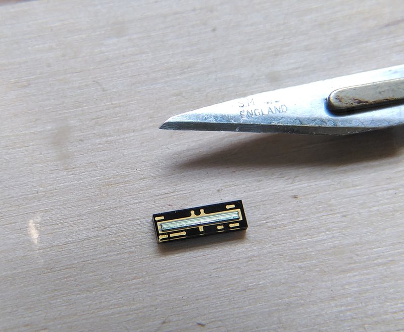
As we have a lot of robots to adapt, we need a cheap solution to line following navigation. The starting point was to build an array of 6 photo-interruptor sensors we had left over from the viruscraft project. These comprise an individual LED and photosensor, and can work really well for line following with wheeled robots, as they can be extremely close to the floor - but I could not get these to work from further away than 10mm or so. We needed a light sensor that could be focused - and ideally a better resolution too. Luckily we found an 128x1 pixel "photoarray" sensor (TSL1401) which are around £7 each that we can use. This is mostly used for bar code scanning, only reads greyscale but can be run much faster than normal cameras if required.
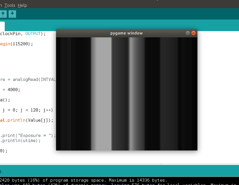
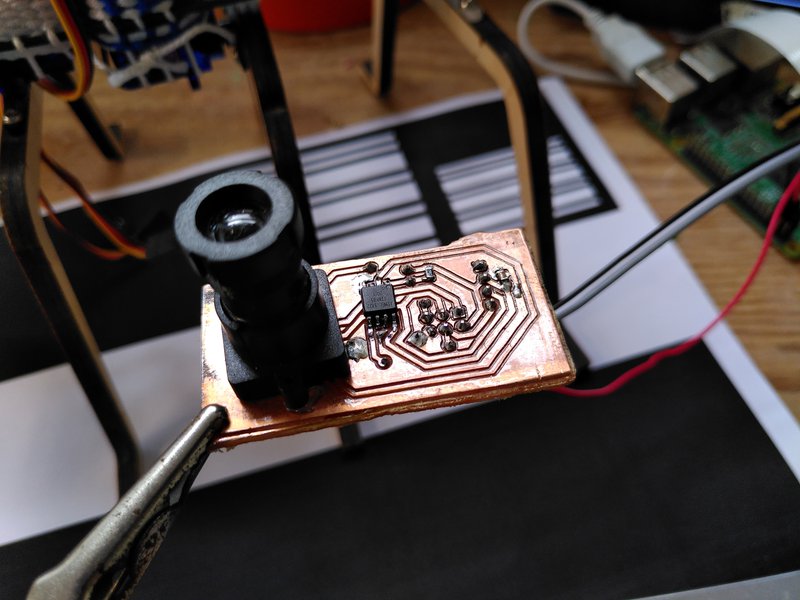
This takes a bit of tricky soldering - and the need for a lens to focus the light in the right way. We tried a few different ones but the best option turned out to be the lens dismantled from an old Playstation 2 EyeToy camera as it has an adjustable focus. Using an Arduino you can stream the data over serial to view the image live, and although it takes a while to understand what you are looking at - you can use a test pattern and set the focus so it's sharp.
To actually test if this was going to work we needed to quickly mill a small PCB to mount the sensor and a processor to read it that could fit on our robots. This was a good test of our new CNC machine as these surface mount parts require much more precise cuts than through-hole components (we've previously used other companies for this sort of job).
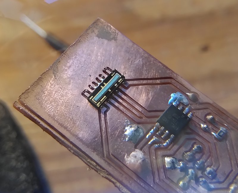
The other tricky thing with this sensor is that the pads are all underneath the body of the component so you have to use solder paste and a heat gun, and you can't visually check if it's worked. The sensor also has a tolerance of 300 degree temperatures for only a few seconds, so the trick here is to heat the board from underneath first. I was quite worried about this, but it was much easier than it sounds - I think we'll be using solder paste a bit more in future as it's less messy than conventional soldering.
The sensor is actually an analogue device, with a variable exposure - so it's pretty interesting what you can get it to do. Pattern recognition in one dimension is quite an odd thing too - but all the usual operations you'd use in 2D apply, averaging pixels and finding features in the "image". We are using a very small (ATTiny85) microprocessor as a pattern recognition "co-processor" so we don't need to use the main one and interfere with the servos and radio that need precise timing. There is something quite satisfying by increasing your processing availability by just doing some soldering.
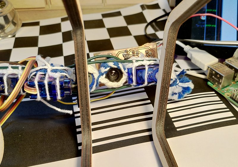
The lens/PCB assembly handily fits in the existing woven structure really well, pointing down. It needs to be at the front of the robot so the centre of rotation is behind it (this means we are actually in reverse direction to previously, but this has no real affect on the robot walking abilities).
The pattern recognition process works like this:
- Calibrate the exposure first at startup by taking the average pixel value and subtracting the difference from the exposure time in milliseconds until it balances out. (We tried running this continually to start with, but it's better to do it periodically when at a point you know both the line and background are present in the image to avoid false positives).
- Search the image for light and dark "features" - defined simply by searching for crossing points above and below the average value.
- Filter these features by their size - our lines turn out to be around 30 pixels wide.
- If we have a feature that matches, find its centre position. If this drifts by 5 or more pixels from the centre of the image (pixel 64) then it indicates that we need to adjust our orientation.
A note on the implementation of all this: the robots all have a virtual machine running on them which means we can send compiled Lisp programs over the radio link from a Raspberry Pi in the form of bytecode. This setup means we can remotely livecode the robots in a high level language which is really handy to quickly get things working without having to continually plug in a programmer when it's walking around. The pattern recognition runs on its own but can be read and controlled by the Lisp code via an i2c interface alongside the other sensors on board.
The way the robots walk is that the front and back legs move together to provide the forward/backward motion while the centre legs rotate in the other axis, and effectively change the resistance of the feet on the left or the right of the robot with the floor. This means by changing the period of the central legs we can change direction, and by slightly changing the centre point (or bias) of their rotation we can make the robot gradually turn.
The Lisp code we are running describes a state machine, which currently has four states:
- Line is in the centre - walk forwards
- Line is to the left or right - attempt to turn back towards the line
- Line is lost - keep doing the last movement (this often recovers the line)
- Line is lost and we've been doing the last movement for "too long" - walk in reverse (this can mean, as in the video - that the robot retraces its steps and can find the line again).
This simple setup results in complex behaviour from a viewers perspective, and is quite different to the may pole dances we've done before as now it is now much more clearly reacting to its environment. The manner in which these robots move is not consistent at all, tiny changes in the floor or differences in how the cheap servos respond can alter its movements in drastic ways - this approach to navigation works because it can react to these inconsistencies directly and self correct. This approach reminds of the (now weirdly unfashionable) observation that the complexity of a something we consider "intelligent" has its roots mainly in the complexity of its environment - and has less to do with its internal structures as we might like to think.
Currently these movements are kept deliberately slow, moving a bit and stopping to allow the robot to come to rest before taking another measurement. The next step is to speed it up and test how it deals with more complex routes and crossings between multiple paths, and then finally try this with multiple robots!
There is an exciting possibility that we can use the same navigation system to simultaneously read bar codes to give us more information - for example this would allow each robot to knows what tile it is currently on, and so prevent collisions by making them wait in line for each other, and even sequence the resulting dance as a group.
Created: 15 Jul 2021 / Updated: 23 Oct 2021


